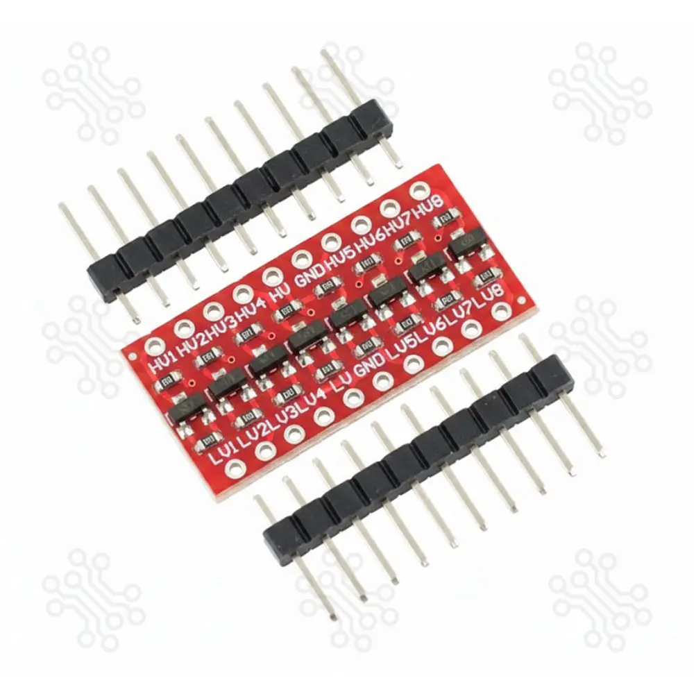
Description of Logic Level Converter Bi Directional 8 Channel The Logic Level Converter Bi Directional 8 Channel is a high-performance solution for connecting two different voltage logic circuits. It is primarily used to bridge the gap between 3.3V and 5V systems, ensuring safe communication between microcontrollers, sensors, and high-voltage peripherals. Key Features The module features 8 independent channels that can convert up to 8 logic signals simultaneously. It is highly versatile and can convert between 3.3V, and 5V logic circuits. The design is bi-directional, allowing it to work seamlessly with bi-directional buses such as I2C. The circuit utilizes N-Ch MOSFET transistors for efficient and reliable level translation. Technical Specification Feature Details Channels 8 Bi-directional Channels Voltage Support 1.8V / 2.8V / 3.3V / 5.0V Circuit Type MOSFET-based Level Shifting Protocol Support I2C (up to 400kHz), UART, TTL Serial Footprint (DIP-20 (0.45″ row-to-row) Dimension 28mm x 14mm Module Operation To use the module, you hook up the two voltages that you want to convert between to the LV (low Voltage) and HV (High Voltage) inputs. The higher voltage is always connected to the HV side. If using with an Arduino, you would typically connect the 3.3V output of the Arduino to the Low Voltage (LV) input and the 5V output of the Arduino to the High Voltage (HV) input. There are two grounds on the board as well. These aren’t used by the circuit on the board, but can be used to pass a ground connection along with the data between the systems if it is needed. You then hook-up the lower voltage logic signals to the LV1-LV8 pins and the higher voltage logic signals to the corresponding HV1-HV8 pins (LV1 connects to HV1, etc) and you are set to go. There is no direction control required for the bi-directional functionality. MOSFET translators like this are best used for slow to moderate speed signals. They will typically work fine at I2C 400kHz type speeds, but may or may not work reliably with high speed signals like SPI. Module Connections (Pinout Guide) For optimal performance, ensure the higher voltage is always connected to the HV side. HV (High Voltage): Connect to the higher voltage source (typically 5V). LV (Low Voltage): Connect to the lower voltage source (typically 3.3V). GND (x2): Ground pins to share a common reference between two voltage systems. Signal Mapping: HV1 to HV8: High-voltage side signal pins. LV1 to LV8: Corresponding low-voltage side signal pins (e.g., LV1 connects to HV1). Application Arduino with 3.3V sensors (BME280, MPU6050) Raspberry Pi with 5V modules ESP8266 / ESP32 with 5V relay modules I2C communication (LCD, OLED, RTC modules)` SPI devices (SD card module, TFT display) UART communication (GPS module, GSM module) Interfacing 5V ultrasonic sensor with 3.3V microcontroller Mixed-voltage robotics and embedded project Packaging Details 1 x Logic Level Converter Bi Directional 8 Channel 2 x Male Header Connector 10 pin (DIP-20 (0.45″ row-to-row) Warranty and Replacement TechShopBD offers up to one year of warranty and replacement support for its products, depending on the supplier(s) and product(s). The specific warranty duration for each product can be found on the respective product page. To be eligible for warranty and replacement support, customers must agree to our terms and conditions. Attention Note: This item is non-returnable. If this item arrives damaged or is not functioning properly, please don’t hesitate to contact us to determine if further action is required. Need Help? Our engineers are available to assist you. If you have any queries, please leave a comment below or call 09678110110 from 09:00 am to 06:00 pm (7 days a week). You can also reach us via WhatsApp or Facebook Inbox


.jpg)