$32.7
$57.88
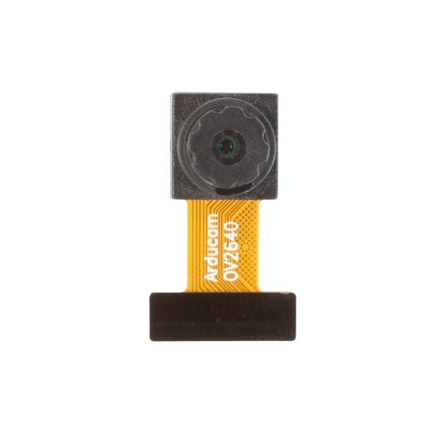
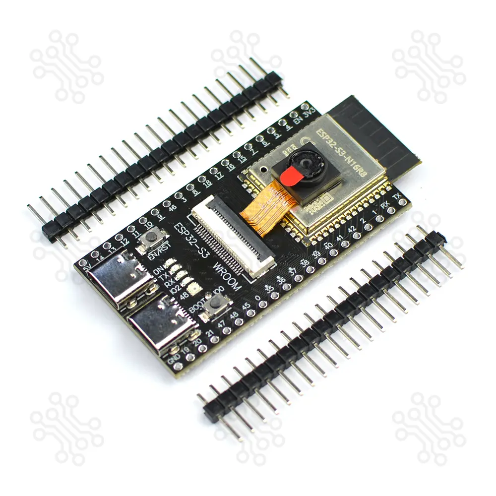
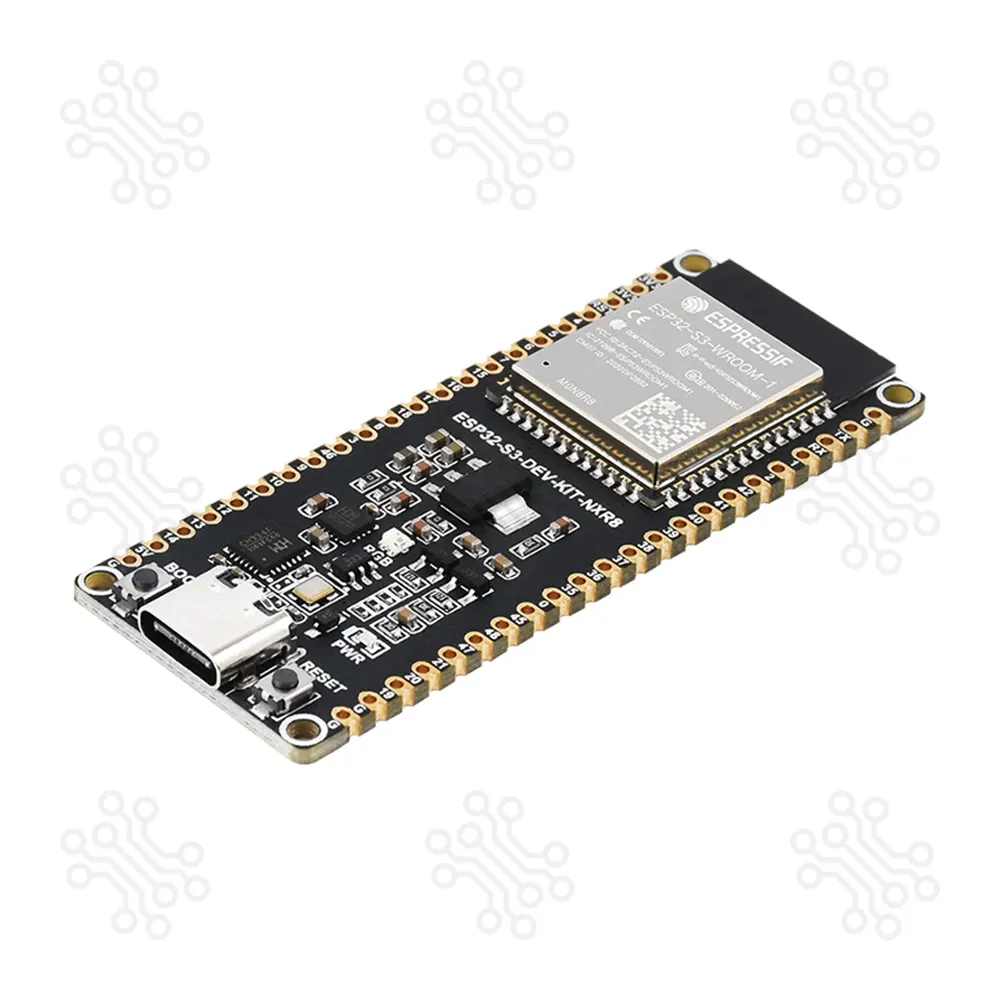
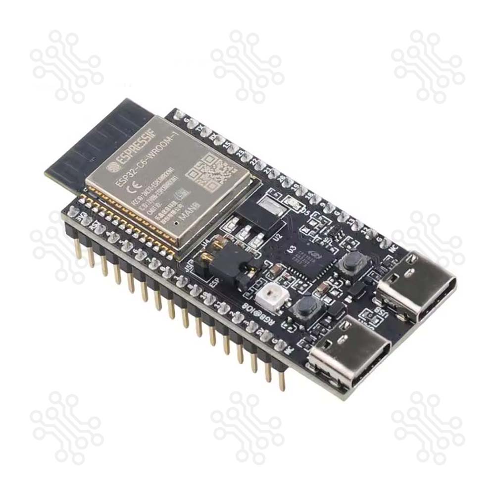
Description of ESP32 S3 WROOM N16R8 WiFi Bluetooth CAM Development Board The ESP32-S3-WROOM-N16R8 Wi-Fi Bluetooth CAM Development Board is an entry-level development board equipped with ESP32-S3-WROOM-1 a general-purpose Wi-Fi Bluetooth Low Energy MCU module that integrates complete Wi-Fi and Bluetooth Low Energy functions. It perfect for AI, IoT, and advanced embedded applications. The board features a dual-core Xtensa LX7 processors, 16 MB flash memory, and 512 KB RAM, which helps it handle image capture, basic AI tasks, and wireless communication smoothly. It comes with an included OV2640 camera module, allowing users to start camera and vision projects easily without needing extra hardware. The board also has Dual USB ports, making power supply and programming more convenient. Most of the module’s I/O pins are easily accessible through the pin headers located on both sides of the board. Developers can connect various peripherals using jumper wires or place the board directly on a breadboard. Before use, the header pins must be soldered onto the board. Technical Specification Parameter Function Details Flash Memory Storage 16 MB embedded flash for program and data storage RAM Memory 512 KB internal RAM for program execution Wireless Connectivity Communication WiFi 802.11 b/g/n and Bluetooth 5.0 support I/O Pins GPIO Access 34 multifunction GPIO pins Operating Voltage Power Requirement 3.3V operation Power Supply Input Power USB-C or external 5V supported Analog Interfaces Analog & Touch 2 × 12-bit SAR ADC, temperature sensor, 14 touch pins Digital Interfaces Peripherals 4 SPI, 3 UART, 2 I2C, 2 I2S, RMT, PWM, CAN, SDIO Camera Interface Imaging 1 × DVP (8-bit–16-bit) Display Interface Display Output LCD (8-bit), RGB (16-bit); supports RGB565, YUV422/420/411 USB Interface Programming & Debugging 1 Full-Speed USB OTG 1 USB Serial/JTAG controller Timers Timing Control 4 × 54-bit timers, 1 × 52-bit system timer, 3 watchdog timers DMA Channels Data Transfer 5 TX 5 RX general-purpose DMA channels Temperature Range Operating Range -40°C to 65°C Board Dimensions Size 57 mm × 28 mm Note: For boards with Octal SPI flash/PSRAM memory embedded ESP32-S3-WROOM-1 modules, the pins GPIO35, GPIO36 and GPIO37 are used for the internal communication between ESP32-S3 and SPI flash/PSRAM memory, thus not available for external use. Power Supply Options There are three mutually exclusive ways to provide power to the board: USB-to-UART Port and ESP32-S3 USB Port (either one or both), default power supply (recommended) 5V and G (GND) pins 3V3 and G (GND) pins ESP32-S3-DevKitC-1 Pinouts Header Block The two tables below provide the Name and Function of the pins on both sides of the board (J1 and J3). J1 No. Name Type Function 1 3V3 P 3.3 V power supply 2 RST I EN 3 4 I/O/T RTC_GPIO4, GPIO4, TOUCH4, ADC1_CH3 4 5 I/O/T RTC_GPIO5, GPIO5, TOUCH5, ADC1_CH4 5 6 I/O/T RTC_GPIO6, GPIO6, TOUCH6, ADC1_CH5 6 7 I/O/T RTC_GPIO7, GPIO7, TOUCH7, ADC1_CH6 7 15 I/O/T RTC_GPIO15, GPIO15, U0RTS, ADC2_CH4, XTAL_32K_P 8 16 I/O/T RTC_GPIO16, GPIO16, U0CTS, ADC2_CH5, XTAL_32K_N 9 17 I/O/T RTC_GPIO17, GPIO17, U1TXD, ADC2_CH6 10 18 I/O/T RTC_GPIO18, GPIO18, U1RXD, ADC2_CH7, CLK_OUT3 11 8 I/O/T RTC_GPIO8, GPIO8, TOUCH8, ADC1_CH7, SUBSPICS1 12 3 I/O/T RTC_GPIO3, GPIO3, TOUCH3, ADC1_CH2 13 46 I/O/T GPIO46 14 9 I/O/T RTC_GPIO9, GPIO9, TOUCH9, ADC1_CH8, FSPIHD, SUBSPIHD 15 10 I/O/T RTC_GPIO10, GPIO10, TOUCH10, ADC1_CH9, FSPICS0, FSPIIO4, SUBSPICS0 16 11 I/O/T RTC_GPIO11, GPIO11, TOUCH11, ADC2_CH0, FSPIID, FSPIIO5, SUBSPID 17 12 I/O/T RTC_GPIO12, GPIO12, TOUCH12, ADC2_CH1, FSPIIO6, SUBSPICLK 18 13 I/O/T RTC_GPIO13, GPIO13, TOUCH13, ADC2_CH2, FSPIIO7, SUBSPIQ 19 14 I/O/T RTC_GPIO14, GPIO14, TOUCH14, ADC2_CH3, FSPIWP, FSPIIO8, SUBSPIWP 20 5V P 5 V power supply J3 No. Name Type Function 1 TX I/O/T U0TXD, GPIO43, CLK_OUT1 2 RX I/O/T U0RXD, GPIO44, CLK_OUT2 3 1 I/O/T RTC_GPIO1, GPIO1, TOUCH1, ADC1_CH0 4 2 I/O/T RTC_GPIO2, GPIO2, TOUCH2, ADC1_CH1 5 42 I/O/T MTMS, GPIO42 6 41 I/O/T MTDI, GPIO41, CLK_OUT1 7 40 I/O/T MTDO, GPIO40, CLK_OUT2 8 39 I/O/T MTCK, GPIO39, CLK_OUT3, SUBSPICS1 9 38 I/O/T GPIO38, FSPIWP, SUBSPIWP, RGB LED 10 37 I/O/T SPIDQS, GPIO37, FSPIQ, SUBSPIQ 11 36 I/O/T SPIIO7, GPIO36, FSPICLK, SUBSPICLK 12 35 I/O/T SPIIO6, GPIO35, FSPID, SUBSPID 13 0 I/O/T RTC_GPIO0, GPIO0 14 45 I/O/T GPIO45 15 48 I/O/T GPIO48, SPICLK_N, SUBSPICLK_N_DIFF 16 47 I/O/T GPIO47, SPICLK_P, SUBSPICLK_P_DIFF 17 21 I/O/T RTC_GPIO21, GPIO21 18 20 I/O/T RTC_GPIO20, GPIO20, U1CTS, ADC2_CH9, CLK_OUT1, USB_D 19 19 I/O/T RTC_GPIO19, GPIO19, U1RTS, ADC2_CH8, CLK_OUT2, USB_D- 20 G G Ground Note: P: Power supply; I: Input; O: Output; T: High impedance. How to Program ESP32 S3 WROOM N16R8? The ESP32 S3 WROOM N16R8 Camera Module is a development board based on ESP32-S3-WROOM-1 modules, which include a microcontroller with Wi-Fi and Bluetooth LE. It exposes most of its I/O pins through headers, allowing you to connect sensors, actuators, and other devices. You can program this board using different IDE platforms, depending on your preference and project type. The most common options are: Arduino IDE – simple and beginner-friendly, ideal for quick testing or IoT projects. ESP-IDF – the official framework from Espressif, more powerful for advanced features and performance tuning. Before programming, make sure: You have a USB cable to connect the board. Your computer recognizes the board’s USB-to-serial interface. You can test the board by uploading the Camera Web Server for ESP32-S3 example using the Arduino IDE. Install ESP32 support in Arduino IDE Follow the guide: “Installing ESP32 Board in Arduino IDE”. Select the board Go to Tools → Board and choose ESP32S3 Dev Module. Write the code Camera-Web-Server-for-ESP32S3 Application The ESP32 S3 WROOM N16R8 Wi-Fi Bluetooth CAM Development Board is ideal for: IoT Projects Home Automation AIoT Applications Robotics Control USB-Based Development Wireless Communication Packaging Detail 1 × ESP32 S3 WROOM N16R8 Wi-Fi Bluetooth CAM Development Board 1 × OV2640 Camera 2 × Male Header Connector (20 Pin) Document ESP32-S3-WROOM-1 Datasheet OV2640 Camera Warranty and Replacement TechShopBD offers up to one year of warranty and replacement support for its products, depending on the supplier(s) and product(s). The specific warranty duration for each product can be found on the respective product page. To be eligible for warranty and replacement support, customers must agree to our terms and conditions. Attention Note: This item is non-returnable. If this item arrives damaged or is not functioning properly, please don’t hesitate to contact us to determine if further action is required. Need Help? Our engineers are available to assist you. If you have any queries, please leave a comment below or call 09678110110 from 09:00 am to 06:00 pm (7 days a week). You can also reach us via WhatsApp or Facebook Inbox
Esp32