$12.09
$22.12
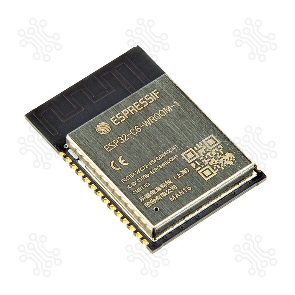
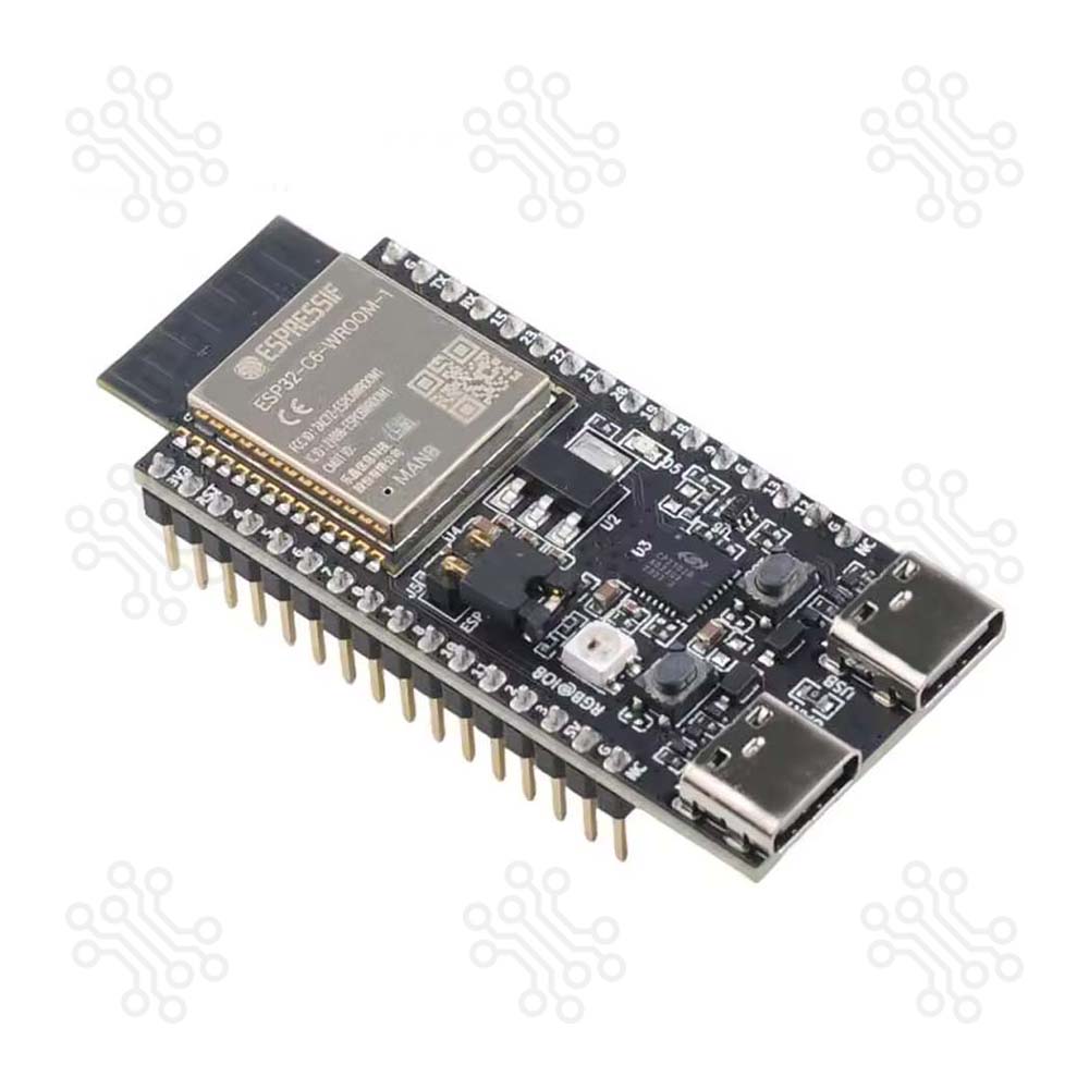
Description of Espressif ESP32 C6 DevKitC 1 Development Board ESP32-C6-DevKitC-1 is an entry-level development board based on ESP32-C6-WROOM-1, a general-purpose module with a 8 MB SPI flash. This board integrates complete Wi-Fi, Bluetooth LE, Zigbee, and Thread functions. Most of the I/O pins are broken out to the pin headers on both sides for easy interfacing. Developers can either connect peripherals with jumper wires or mount ESP32-C6-DevKitC-1 on a breadboard. Technical Specification Parameter Function Details ESP32-C6-WROOM-1 Wireless Module Wi-Fi 6, Bluetooth 5, IEEE 802.15.4; 8 MB flash; WROOM-1 Onboard PCB antenna Pin Header GPIO Access All usable GPIO pins exposed (except flash SPI) 5 V to 3.3 V LDO Power Regulation Converts 5 V input to stable 3.3 V output 3.3 V Power On LED Power Indicator Turns on when USB power is supplied USB-to-UART Bridge USB–UART Interface Supports communication up to 3 Mbps ESP32-C6 USB Type-C Port Native USB Interface USB 2.0 full-speed (12 Mbps); used for power, flashing, USB communication, JTAG Boot Button Firmware Download Used with Reset to enter Firmware Download mode Reset Button System Reset Restarts the board USB Type-C to UART Port Power & UART Communication Used for power supply, firmware flashing, and UART communication RGB LED Status Indicator Addressable LED controlled by GPIO8 J5 Header Current Measurement Provides access point for current monitoring Block Diagram The block diagram below shows the components of ESP32-C6-DevKitC-1 and their interconnections. Power Supply Options There are three mutually exclusive ways to provide power to the board: USB Type-C to UART Port and ESP32-C6 USB Type-C Port (either one or both), default power supply (recommended) 5V and GND pin headers 3V3 and GND pin headers Current Measurement The J5 headers on ESP32-C6-DevKitC-1 (see J5 in Figure ESP32-C6-DevKitC-1 - front) can be used for measuring the current drawn by the ESP32-C6-WROOM-1 module: Remove the jumper: Power supply between the module and peripherals on the board is cut off. To measure the module’s current, connect the board with an ammeter via J5 headers. Apply the jumper (factory default): Restore the board’s normal functionality. Note: When using 3V3 and GND pin headers to power the board, please remove the J5 jumper, and connect an ammeter in series to the external circuit to measure the module’s current. Pin Layout Safe Pins to Use These pins are safe for general GPIO usage without boot or system conflicts: IO0, IO1, IO2, IO3, IO10, IO11, IO20, IO21, IO22, IO23 Why Are These Pins Safe? No boot sequence involvement; no flash/PSRAM connections; no USB or JTAG conflicts; freely assignable without issues PIN Label Why Avoid Type IO4 MTMS Used during boot; required for JTAG debugging; flash data in internal-flash models Strapping IO5 MTDI Used during boot; required for JTAG debugging; flash data in internal-flash models Strapping IO6 MTCK Required for JTAG debugging; connected to flash clock in internal-flash models JTAG IO7 MTDO Required for JTAG debugging; connected to flash data in internal-flash models JTAG IO8 GPIO8 Determines boot mode; pulling low at reset can prevent normal boot Strapping IO9 GPIO9 Pulling low on reset forces the ESP32-C6 into download mode instead of normal boot Strapping IO12 USB_D- Dedicated to USB communication; avoid if using USB functionality USB IO13 USB_D Dedicated to USB communication; avoid if using USB functionality USB IO15 JTAG_SEL Controls JTAG input source at boot; avoid altering its state JTAG IO16 U0TXD Default UART0 transmit pin; may interfere with serial console or programming UART IO17 U0RXD Default UART0 receive pin; may interfere with serial console or programming UART IO18 FSPIQ Connected to internal flash; using as GPIO can disrupt flash operations Flash IO19 FSPID Connected to internal flash; using as GPIO can disrupt flash operations Flash Header Block The two tables below provide the Name and Function of the pin headers on both sides of the board (J1 and J3). The pin header names are shown in Figure ESP32-C6-DevKitC-1 - front. The numbering is the same as in the ESP32-C6-DevKitC-1 Schematic v1.2 (PDF). J1 No. Name Type Function 1 3V3 P 3.3 V power supply 2 RST I High: enables the chip; Low: disables the chip 3 4 I/O/T MTMS, GPIO4, LP_GPIO4, LP_UART_RXD, ADC1_CH4, FSPIHD 4 5 I/O/T MTDI, GPIO5, LP_GPIO5, LP_UART_TXD, ADC1_CH5, FSPIWP 5 6 I/O/T MTCK, GPIO6, LP_GPIO6, LP_I2C_SDA, ADC1_CH6, FSPICLK 6 7 I/O/T MTDO, GPIO7, LP_GPIO7, LP_I2C_SCL, FSPID 7 0 I/O/T GPIO0, XTAL_32K_P, LP_GPIO0, LP_UART_DTRN, ADC1_CH0 8 1 I/O/T GPIO1, XTAL_32K_N, LP_GPIO1, LP_UART_DSRN, ADC1_CH1 9 8 I/O/T GPIO8 10 10 I/O/T GPIO10 11 11 I/O/T GPIO11 12 2 I/O/T GPIO2, LP_GPIO2, LP_UART_RTSN, ADC1_CH2, FSPIQ 13 3 I/O/T GPIO3, LP_GPIO3, LP_UART_CTSN, ADC1_CH3 14 5V P 5 V power supply 15 G G Ground 16 NC – No connection J3 No. Name Type Function 1 G G Ground 2 TX I/O/T U0TXD, GPIO16, FSPICS0 3 RX I/O/T U0RXD, GPIO17, FSPICS1 4 15 I/O/T GPIO15 5 23 I/O/T GPIO23, SDIO_DATA3 6 22 I/O/T GPIO22, SDIO_DATA2 7 21 I/O/T GPIO21, SDIO_DATA1, FSPICS5 8 20 I/O/T GPIO20, SDIO_DATA0, FSPICS4 9 19 I/O/T GPIO19, SDIO_CLK, FSPICS3 10 18 I/O/T GPIO18, SDIO_CMD, FSPICS2 11 9 I/O/T GPIO9 12 G G Ground 13 13 I/O/T GPIO13, USB_D 14 12 I/O/T GPIO12, USB_D- 15 G G Ground 16 NC – No connection Note 1 P: Power supply; I: Input; O: Output; T: High impedance. 2 Used to drive the RGB LED. 3 (1,2,3,4,5) MTMS, MTDI, GPIO8, GPIO9, and GPIO15 are strapping pins of the ESP32-C6 chip. These pins are used to control several chip functions depending on binary voltage values applied to the pins during chip power-up or system reset. For description and application of the strapping pins, please refer to ESP32-C6 Datasheet > Section Strapping Pins. How to program the ESP32-C6? The ESP32-C6 is a next-generation MCU that supports Wi-Fi 6, BLE 5, Thread, and Matter. You can program it using several IDEs. Arduino IDE allows simple coding for beginners. ESP-IDF is used for advanced projects. PlatformIO provides a clean and flexible workflow in VS Code. Thonny IDE allows programming with MicroPython. Please proceed to ESP-IDF Get Started, which will quickly help you set up the development environment then flash an application example onto your board. Application IoT Prototyping & Wireless Sensor Networks Smart Home and Building Automation BLE Beacons and Gateways Zigbee/Thread-enabled Devices Wearables and Health Monitoring USB-Enabled Embedded Applications Educational and Industrial Prototyping Document ESP32-C6 Datasheet (PDF) ESP32-C6-WROOM-1 Datasheet (PDF) ESP32-C6-DevKitC-1 Schematic v1.2 (PDF) ESP32-C6-DevKitC-1 PCB Layout (PDF) ESP32-C6-DevKitC-1 Dimensions (PDF) ESP32-C6-DevKitC-1 Dimensions source file (DXF) ESP32 C6 Based Projects ESP32 C6 দিয়ে Zigbee ডিভাইস Packaging Detail 1 X Espressif ESP32-C6-DevKitC-1 Development Board Warranty and Replacement TechShopBD offers up to one year of warranty and replacement support for its products, depending on the supplier(s) and product(s). The specific warranty duration for each product can be found on the respective product page. To be eligible for warranty and replacement support, customers must agree to our terms and conditions. Attention Note: This item is non-returnable. If this item arrives damaged or is not functioning properly, please don’t hesitate to contact us to determine if further action is required. Need Help? Our engineers are available to assist you. If you have any queries, please leave a comment below or call 09678110110 from 09:00 am to 06:00 pm (7 days a week). You can also reach us via WhatsApp or Facebook Inbox
Esp32